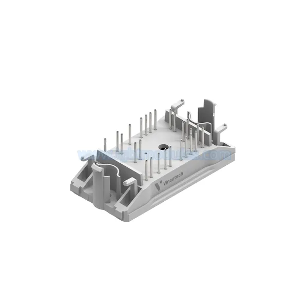
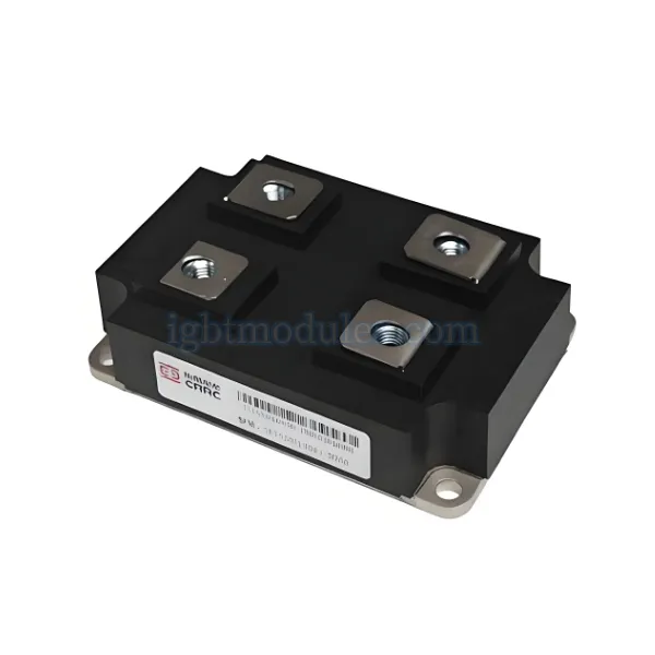
1 - 3300V 500A SiC Hybrid Module
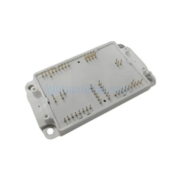
CRRC Times Semiconductor has launched a 3300V/500A SiC hybrid module suitable for rail transit traction systems. This module adopts self-developed IGBT chips and SBD Schottky barrier diodes, relying on a mature process platform. It has zero reverse recovery characteristics, can significantly reduce switching losses, increase switching frequency, has low thermal resistance and good thermal conductivity, providing solutions for compact, miniaturized, and high-efficiency converter design for users.
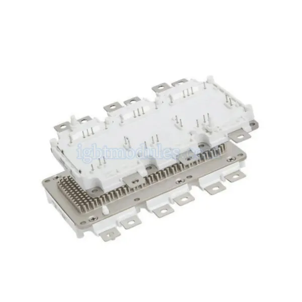
3300V/500A SiC Hybrid Module Parameters:
IGES+: 100nA
| Parameter | Value |
|---|---|
| VCES | 3300V |
| IC | 500A |
| VCE(sat) | 2.2V @ 25C |
| VGE(th) | 6.2V |
| ICES | 25mA |
| IGES- | -110nA |
| VF | 2.1V |
Table 1: Static Parameters of 3300V/500A SiC Hybrid Module
| Parameter | Value |
|---|---|
| Dynamic Parameters |
(IC = 500A, VCC = 1800V, VGE = 15V, RG(ON) = RG(OFF) = 4.5ohm, Cge = 100nF, Tj = 150C)
| Parameter | Value |
|---|---|
| EON | 1100 mJ |
(VCC = 1800V, IF = 500A, diF/dt = 1700A/us, Tj = 150C)
| Parameter | Value |
|---|---|
| EOFF | 1310 mJ |
| Erec | 32 mJ |
| Qrr | 50 uC |
| Parameter | Value |
|---|---|
| Irr | 95A |
Table 2: Dynamic Parameters of 3300V/500A SiC Hybrid Module
- Under the same test conditions, comparing the switching loss data of Si-based IGBT modules and SiC hybrid modules, as shown in Table 3. The loss generated by one switching cycle of the IGBT module is 3280mJ, while the loss generated by one switching cycle of the SiC hybrid module is 2090mJ, a reduction of approximately 32.6%.
- The 3300V/500A SiC hybrid module has a better positive temperature coefficient, which is beneficial for module parallel connection. Its thermal resistance is significantly reduced, providing greater current capability margin. The reverse recovery energy is extremely low, and turn-on loss and total loss are greatly reduced. The good reverse recovery characteristics of SBD provide a larger safe operating area, which is beneficial for module reliability under extreme application conditions. It can improve the efficiency and performance of traction converters in the rail transit field.
2 - Characteristics of SiC-SBD Devices - Why Minimum Loss Matters
2-1 Recovery Characteristics of SiC-SBD
- When Si-FRD switches from forward to reverse direction, a large transient current is generated. During this period, it transitions to a reverse bias state, resulting in significant losses. This is because minority carriers accumulated in the drift layer during forward conduction continue to conduct electricity until they disappear (this time is also called the storage time). The larger the forward current, or the higher the temperature, the larger the recovery time and recovery current, and thus the greater the loss.
- In contrast, SiC-SBD is a majority carrier device (unipolar device) that does not use minority carriers for electrical conduction. Therefore, the phenomenon of minority carrier accumulation does not occur in principle. Since only a small current equivalent to discharging the junction capacitance is generated, compared with Si-FRD, the loss can be significantly reduced.
- Moreover, this transient current basically does not change with temperature and forward current, so regardless of the environment, fast recovery can be achieved stably. In addition, it can also reduce noise caused by the recovery current, achieving noise reduction effects.
2-2 Dependence on Forward Current and Temperature
- Currently, SiC SBDs at voltage levels of 600V, 1200V, 1700V, and 3300V have been commercialized. SiC SBDs above 3300V are also being researched globally.
- Compared with Si-FRD, SiC-SBD has obvious advantages in both forward conduction and reverse recovery characteristics. Therefore, if SiC-SBD replaces the current mainstream product fast recovery diodes (FRD), recovery losses can be significantly reduced. This is beneficial for improving power supply efficiency, and through high-frequency driving, miniaturization of passive devices such as inductors can be achieved, and noise can be reduced.
- The devices are widely used in air conditioners, power supplies, power conditioners in photovoltaic power generation systems, power factor correction circuits (PFC circuits) and rectifier bridge circuits in fast chargers for electric vehicles, etc.
3 - Application of SiC SBD Chips in 3300V/500A SiC Hybrid Modules for Traction Applications
- SiC, as a wide bandgap semiconductor material, has advantages compared with Si such as high breakdown field strength, high thermal conductivity, large current carrying capacity, fast switching speed, and ability to operate at high temperatures. It is suitable for applications in high-voltage, high-temperature, and high-frequency fields. At the same time, SiC devices can significantly improve the conversion efficiency of power electronic devices, which is beneficial for energy conservation and environmental protection, as well as high power density and lightweight of devices.
- In terms of full SiC MOSFET modules, CRRC has developed full SiC modules below 1700V, and ROHM has developed full SiC modules below 1200V, which have been applied within a certain range. Research on SiC MOSFETs in China is still in its initial stage. High-voltage high-current SiC MOSFET devices are still in the mechanism research and experimental stage in terms of gate oxide reliability, yield, test drive, and performance detection control. Large-scale commercial application will still take some time.
- Based on the self-developed 3300V/32A SiC SBD, this paper develops a 3300V/500A SiC hybrid module for locomotive traction, tests and analyzes its performance parameters, and compares them with the performance parameters of 3300V/500A IGBT modules. PLECS software is used to simulate the junction temperature of SiC hybrid modules under traction inverter PWM operating conditions.
- To reduce design changes to other components of the converter system, the 3300V/500A SiC hybrid module designed in this paper adopts the package interface dimensions of a standard Si IGBT module of 130mm x 160mm x 38mm. The circuit structure is a dual-switch circuit, with each bridge arm having a rated current capacity of 500A, using two substrates connected in parallel.
- Since a single SiC SBD chip only has a current of tens of amperes, the module requires multiple chips in parallel to achieve the required current capability. The IGBT chips used in this design have a voltage and current rating of 3300V/62.5A, and the SiC SBD chips have a voltage and current rating of 3300V/32.5A. The module contains a total of 16 Si IGBT and 32 SiC SBD chips.
- Interconnection between chips uses wire bonding to achieve high currents, with SiC SBD chips anti-parallel to IGBT chips. To ensure the consistency of chip performance parameters used in the module, the probe test data of SBD chips are sorted, and chips with good VF and ICES consistency are selected. IGBT chips are already widely used in the locomotive field, with good consistency in performance parameters, so no screening processing is required.
- Parasitic inductance, parasitic resistance, junction-to-case thermal resistance, etc., are key factors that need to be considered in module design. The power terminals of the hybrid SiC module adopt a symmetrical structure to form a mutual inductance effect that reduces the internal inductance of the module. The substrate circuit and chip layout adopt a symmetrical design to make the parasitic resistance between chips consistent and minimize inductance differences. Interconnection between SiC SBD chips reduces the distance of bonding wires and increases the current carrying capacity of the wires, achieving current sharing between chips. These factors have been fully optimized and verified in IGBT modules and will not be elaborated further in this paper.
- Compared with IGBT modules, although the process flow of SiC hybrid modules is the same, there are certain differences in process parameters, such as welding and wire bonding parameters. The SiC SBD chip size is 6.1 x 6.1mm. During vacuum reflow soldering, if there is too much solder, chip drift is likely to occur; if there is too little solder, voids will form in the solder layer, affecting chip heat dissipation and thus module reliability.
- The thickness of SiC SBD chips is different from that of Si FRD chips, and the surface metal and process are also slightly different. Wire bonding parameters need to be adjusted and thrust tests performed. Through continuous optimization of the hybrid SiC module packaging process, all process inspection results meet the parameter requirements of locomotive IGBT modules.
3.1 Diode Static Characteristics
- Static performance tests and comparisons were conducted on the packaged modules. The forward characteristic curves of Si FRD and SiC SBD are shown
- The FRD in the IGBT module has a negative temperature coefficient before 300A, while the SBD in the hybrid module has a negative temperature coefficient before 25A. The forward voltage VF of both diodes increases with increasing temperature. SiC SBD has a better positive temperature coefficient, which is beneficial for chip parallel connection and device parallel applications.
- Under a diode forward DC current of 500A, at 25C, 125C, and 150C, the diode forward voltage VF is 2.0V, 3.3V, and 3.8V respectively. This value includes a voltage drop of approximately 0.3V introduced by the current loop parasitic resistance.
- At 25C, the forward voltage of SiC SBD is lower than that of Si FRD, but at high temperatures it is higher than that of Si FRD. Therefore, in terms of chip forward voltage, under high-temperature operating conditions, the conduction loss of SiC SBD alone has no advantage compared with Si FRD.
3.2 Module Dynamic Characteristics
- The dynamic performance of the SiC hybrid module was tested using the double-pulse test. The circuit is shown in Figure 4. During testing, modules serve as mutual test subjects. The upper device is the companion test module, and the lower device is the module under test. After testing, they are swapped.
- The dynamic test waveforms of the 3300V/500A hybrid SiC module are shown in Figure 5. In the evaluation of dynamic testing, during the first pulse, the IGBT of the module under test turns on, and its current rises linearly due to the influence of the load inductor. After the first pulse is turned off, the SiC SBD chip in the module under test performs freewheeling. When the second pulse turns on, the SBD chip in the IGBT module under test is in the reverse recovery process.
- Before the reverse recovery of the SBD chip, current flows through the SBD chip. At this point, the current passing through the load inductor, after being superimposed with the current flowing through the SBD chip, is all applied to the IGBT chip of the module under test. When the reverse recovery of the SBD chip ends, the current of the module under test rises linearly again. When the second pulse is turned off, the IGBT under test can turn off normally.
- The SiC hybrid module integrates IGBT chips and SiC SBD chips. During operation, the two alternately turn on and off. The wide bandgap SiC material itself has certain advantages compared with Si materials. The reverse recovery time of the SiC hybrid module is relatively short. Comparing the reverse recovery waveforms of the SiC hybrid module and the IGBT module, as shown in Figure 6, during the reverse recovery process of the SiC SBD chip, there is almost no recovery current Ir, the tail current is short, and the diode voltage Vr fluctuates slightly, but the reverse recovery loss is very small. Therefore, for the 3300V/500A SiC hybrid module, the reverse recovery energy is almost negligible.
- SiC SBD chips have fast reverse recovery speed, which also has a certain impact on the turn-on of the module. The turn-on waveforms of the SiC hybrid module and the IGBT module are compared and analyzed together, as shown in Figure 7.
- The IGBT, due to the existence of FRD reverse recovery current, ordinary modules will superimpose additional current on the IGBT. The overshoot current will impact the IGBT device, while the reverse recovery current of the SiC hybrid module is much smaller than that of the Si IGBT module, so this overshoot current does not exist. The reduction of turn-on overshoot current greatly reduces the turn-on energy of the device. Due to the small reverse recovery current of the SiC hybrid module, the overvoltage applied to the IGBT chip is significantly reduced, which is beneficial for improving module reliability.
- As the IGBT device drive gate resistance decreases, the turn-on speed increases, and its turn-on energy is greatly reduced. Ordinary IGBT modules are limited by the safe operating area of the FRD and must limit their turn-on speed (turn-on current change rate di/dt). SiC hybrid modules have no safe operating area limitations. SiC hybrid modules can accelerate the turn-on speed of IGBTs, thereby greatly reducing the turn-on energy during application.
- Under the same test conditions, comparing the switching loss data of IGBT modules and SiC hybrid modules, as shown in Table 1. The loss generated by one switching cycle of the IGBT module is 3280mJ, while the loss generated by one switching cycle of the SiC hybrid module is 2090mJ, a reduction of approximately 32.6%.
3.3 Thermal Resistance Characteristics
- Continuous forward DC current IF is an important parameter indicator of the module. This design adopts the structure of a conventional IGBT module, so only the continuous forward DC current of the diode needs to be verified. The continuous forward DC current IF is related to parameters such as the module’s maximum operating junction temperature, case temperature, module thermal resistance, and diode forward voltage (under IF and Tj conditions).
- According to JEDEC 51-1 regulations, by measuring the temperature calibration coefficient of the SiC hybrid module and the power after heating stabilization, a T3ster thermal transient tester is used to obtain the transient response curve, and the results are converted into an integral structure function to obtain the transient thermal impedance curve of the hybrid SiC module
- The junction-to-case thermal resistance of the IGBT chip is 23.5K/kW, and the junction-to-case thermal resistance of the SiC-SBD chip is 36K/kW.
- From the perspective of chip area, the area of a single Si FRD chip is 13.5mm x 13.5mm, and the diode junction-to-case thermal resistance of the IGBT module is 48K/kW. The total area of 4 SiC SBD chips is 12.2mm x 12.2mm. With reduced chip area, the thermal resistance is instead reduced by 25%, fully reflecting the superiority of SiC material’s high thermal conductivity, and increasing the current margin of the diode.
- For the 3300V/500A SiC hybrid module developed in this paper, according to Tj = 150C, Tc = 80C, Vf = 3.8V, the calculated continuous forward DC current IF is approximately 511A, meeting the technical requirements. In addition, SiC SBD chips can operate normally under working conditions greater than 150C. Si FRD cannot compare with SiC SBD. In terms of rated current capacity, the SiC hybrid module has greater margin, so the SiC hybrid module is more reliable.