1. Dynamic Parameter Testing Requirements
1.1 Switching Characterization Fundamentals
Dynamic parameter testing measures the switching behavior of power semiconductor devices under defined voltage, current, and gate drive conditions. Key parameters include turn-on delay time (td(on)), rise time (tr), turn-off delay time (td(off)), fall time (tf), turn-on energy (Eon), turn-off energy (Eoff), and reverse recovery characteristics of body or freewheeling diodes. Accurate measurement of these parameters requires controlled test circuits with low parasitic inductance, precise current and voltage sensing, and synchronization between gate drive and measurement instruments.
1.2 IGBT and SiC Device Testing Considerations
IGBT and SiC MOSFET devices have distinct switching characteristics that require tailored test approaches. IGBT devices exhibit tail current during turn-off due to minority carrier recombination, requiring test systems with sufficient measurement window duration and current sensor bandwidth. SiC MOSFETs switch at faster transition rates and operate at higher frequencies, demanding test systems with higher bandwidth voltage and current measurement capability to capture the rapid switching events. The test system must accommodate the specific gate drive voltage requirements of each device technology, including negative gate bias for IGBT turn-off and appropriate gate resistance selection for SiC devices.
1.3 Production Testing vs. R&D Testing
R&D testing requires comprehensive parameter characterization across a wide range of operating conditions, including temperature, voltage, current, and gate drive variations. Production line testing focuses on rapid pass/fail evaluation of key parameters at defined test points, with throughput and reliability being primary concerns. The test equipment must support both use cases, with the QTJT-D system designed for in-depth laboratory characterization and the QTJ8600T system optimized for automated production testing workflows.
2. Bronze Test Equipment Product Overview
Bronze QTJ Technology offers a range of power device test equipment for dynamic parameter characterization and production testing. The following table compares the key specifications of three test system products.
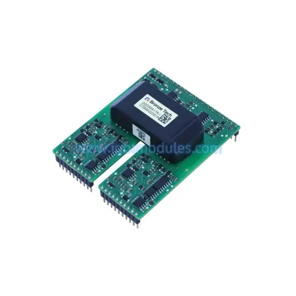
Figure: Dynamic parameter test system for IGBT and SiC power device characterization.
2.1 Product Comparison Table
| Model | Voltage | Current | Power | Package | Applications |
|---|---|---|---|---|---|
| QTJT-D | Up to 6500V | Up to 3000A | N/A (Test System) | Benchtop / Rack | IGBT/SiC dynamic testing, R&D testing |
| QTJ8600T | Up to 1700V | Up to 600A | N/A (Test System) | Production Rack | Production line testing, IGBT/SiC testing |
| QTJ15610A | 15V (Gate Drive) | 10A Peak | N/A (Generator) | Benchtop | Pulse signal generation, R&D testing |
3. Dynamic Parameter Test System Architecture
3.1 QTJT-D Comprehensive Test Platform
The QTJT-D dynamic parameter test system is a comprehensive platform for characterizing the switching behavior of IGBT and SiC power devices under controlled conditions. The system supports voltage ratings up to 6500V and current ratings up to 3000A, accommodating a wide range of device types from low-voltage MOSFETs to high-voltage IGBT modules. The test system includes a programmable DC power supply, inductive load circuit, gate drive unit, and high-bandwidth voltage and current measurement circuits, integrated into a unified test platform with automated test sequence control.
3.2 Switching Energy and Loss Measurement
The QTJT-D system measures turn-on energy (Eon) and turn-off energy (Eoff) by integrating the product of device voltage and current during the switching transition. Accurate energy measurement requires synchronized voltage and current sensing with sufficient bandwidth to capture the switching waveforms without distortion. The test system employs coaxial current shunt or Rogowski coil current sensors and high-bandwidth voltage probes to ensure measurement accuracy across the range of switching speeds encountered in IGBT and SiC device testing.
3.3 Reverse Recovery Characterization
For devices with integral or external freewheeling diodes, the QTJT-D system measures reverse recovery parameters including peak reverse current (Irr), reverse recovery time (trr), and reverse recovery charge (Qrr). These parameters are critical for evaluating the performance of the diode in switching applications and for understanding the interaction between the diode recovery characteristics and the switching behavior of the complementary device in a half-bridge configuration.
4. Production Line Testing with QTJ8600T
4.1 Automated Test Sequence and Throughput
The QTJ8600T production line test system is designed for automated pass/fail testing of IGBT and SiC devices in a manufacturing environment. The system supports voltage ratings up to 1700V and current ratings up to 600A, covering the range of devices commonly used in automotive and industrial applications. Automated test sequences execute predefined test steps including leakage current, threshold voltage, on-state voltage, and dynamic switching parameter verification, with test results evaluated against programmable pass/fail limits for high-throughput production screening.
4.2 Device Handling and Interface
The QTJ8600T system integrates with automated device handling equipment for production line operation, supporting contactor-based testing of discrete devices and test socket interfaces for module-level testing. The test interface design minimizes parasitic inductance and resistance to ensure measurement accuracy and repeatability. System software provides statistical process control (SPC) data collection and reporting, enabling real-time monitoring of production quality and early detection of process drift.
4.3 Test Program Development and Customization
The QTJ8600T system includes software tools for developing and customizing test programs, allowing production engineers to define test parameters, limits, and sequences for specific device types. The software supports import of test specifications from device datasheets and provides a library of standard test routines for common IGBT and SiC device parameters. Test programs can be validated against reference devices and locked to prevent unauthorized modifications in the production environment.
5. Pulse Signal Generation and Test Support
5.1 QTJ15610A Pulse Signal Generator
The QTJ15610A pulse signal generator provides the gate drive signals required for dynamic parameter testing of power semiconductor devices. With a 15V output voltage range and 10A peak current capability, the generator can drive the gate of IGBT and SiC devices under test with configurable pulse width, frequency, and duty cycle. The generator supports single-pulse and multi-pulse test modes, enabling measurement of switching parameters under both transient and thermal steady-state conditions.
5.2 Gate Drive Configuration Flexibility
The QTJ15610A generator allows configuration of gate drive parameters including on-state voltage, off-state voltage (negative bias), gate resistance, and inter-pulse delay. This flexibility enables testing of devices under the specific gate drive conditions used in their target application, providing measurement results that reflect actual operating behavior. The generator output stage is designed for low output impedance and fast transition times, ensuring that the measured switching behavior represents the device characteristics rather than the limitations of the test equipment.
5.3 Integration with Measurement Instruments
The QTJ15610A generator includes trigger output signals for synchronizing oscilloscopes and other measurement instruments with the gate drive pulse. This synchronization ensures that measurement instruments capture the switching event at the correct time, with appropriate pre-trigger and post-trigger record lengths. The generator can be integrated with the QTJT-D test system or used as a standalone instrument in custom test setups, providing the gate drive capability needed for research and development testing of new power device technologies.