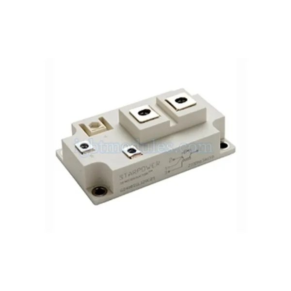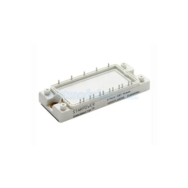
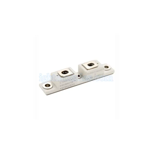
1. Power Diode Portfolio
Standard recovery diodes for line frequency; Fast recovery diodes (FRD) for medium frequency; Ultra-fast recovery diodes for high frequency; Schottky barrier diodes for low voltage drop; Voltage ratings: 200V to 6500V
2. Diode Types and Characteristics
Each diode technology offers a different balance of forward voltage drop and reverse recovery performance.
Comparison Table
| Diode Type | Reverse Voltage | Recovery Speed | Primary Application |
|---|---|---|---|
| Standard Recovery | 200V – 6500V | Slow (µs range) | Line-frequency rectification |
| Fast Recovery (FRD) | 200V – 1200V | Fast (50-500ns) | Switch-mode power supplies |
| Ultra-Fast | 200V – 600V | Very fast (20-100ns) | High-frequency converters |
| Schottky | 20V – 200V | Fastest (no recovery) | Low-voltage DC-DC |
Standard Recovery Diodes
Conventional PN junction diodes offer low forward voltage at line frequencies but have longer reverse recovery times.
• Low Vf for minimum conduction loss; Suitable for 50/60Hz rectification; High surge current capability; Used in power supply input rectifiers
Fast Recovery Diodes (FRD)
Fast recovery diodes are engineered with controlled carrier lifetime to achieve short reverse recovery times.
• Recovery times from tens to hundreds of nanoseconds; Optimized for switching power supplies; Used as freewheeling diodes with IGBTs; Soft recovery for low EMI
3. Application Scenarios
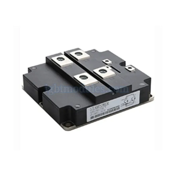
Power diodes serve fundamental roles in virtually all power electronic systems.
Rectification
Converting alternating current to direct current is the most basic diode application.
• Single-phase and three-phase bridge rectifiers; Input rectifiers for power supplies; Battery charging circuits; Welding power supplies
Freewheeling and Snubber
Diodes provide current paths for inductive loads during switch turn-off.
• Freewheeling diodes for motor drives; Flyback diode for relay and solenoid circuits; Snubber diode-capacitor networks; Clamping and voltage protection
4. Selection Considerations
Proper diode selection ensures reliable and efficient circuit operation.
• Select reverse voltage with sufficient safety margin; Evaluate forward current and power dissipation; Match recovery speed to switching frequency; Consider surge current and thermal cycling; Verify package thermal resistance
5. Find the Right Solution for Your Application
Building a rectifier or power supply design? Explore power diode and fast recovery diode options with various voltage, current, and recovery speed ratings to meet your application requirements.
6. Frequently Asked Questions
1:What is the difference between standard and fast recovery diodes?
Standard recovery diodes have longer reverse recovery time and lower forward voltage drop, making them suitable for line-frequency rectification at 50 or 60Hz where switching speed is not critical. Fast recovery diodes have shorter reverse recovery time, typically under 1 microsecond, but slightly higher forward voltage, making them necessary for high-frequency switching applications like switch-mode power supplies and IGBT freewheeling circuits where reverse recovery losses would otherwise be excessive.
2:How do I calculate the current rating for a power diode?
Diode current ratings are typically specified as average forward current at a specific case temperature and conduction angle. For rectifier applications, calculate the RMS current through each diode and compare with the rated RMS current. Apply appropriate derating, typically 20 to 30 percent, for reliability. Also consider surge current capability for inrush conditions, and verify that junction temperature stays within limits under worst-case operating conditions.
3:Can I parallel power diodes for higher current?
Yes, power diodes can be paralleled for increased current capability, but current sharing must be ensured. For proper sharing, use diodes of the same type and from the same manufacturing batch for matched forward voltage characteristics, ensure symmetric thermal conditions with the same heat sink and cooling, use symmetric bus bar or PCB layout with equal impedance paths, and consider adding small balancing resistors or using current-matched devices from the same grade.