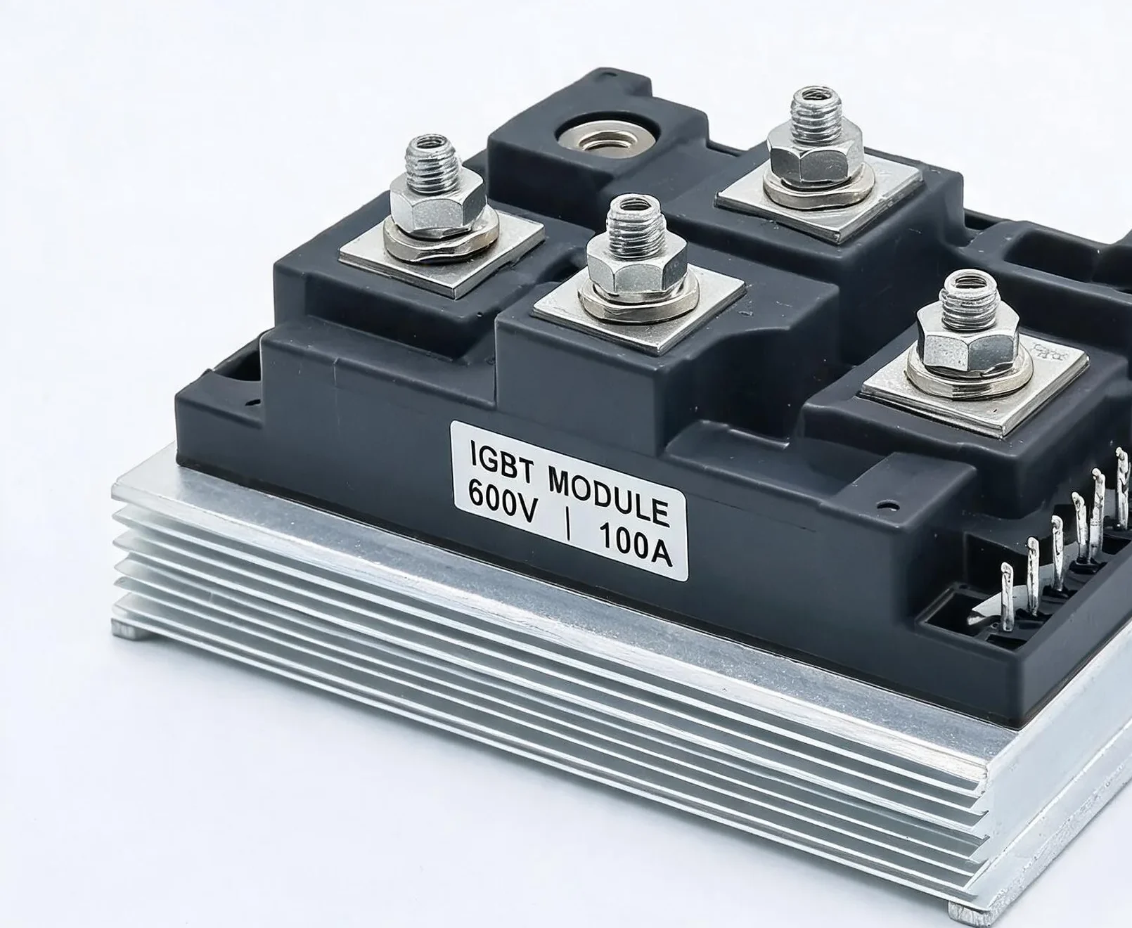
IGBT Module Terminology Glossary and Parameter Definitions
IGBT (Insulated Gate Bipolar Transistor) modules are the core power devices in modern power electronics systems, involving numerous technical terms and parameters. This article comprehensively compiles key IGBT module terminology definitions, covering five major categories: voltage parameters, current parameters, switching characteristics, thermal parameters, and diode parameters, providing an authoritative terminology reference for power electronics engineers.
IGBT Module Terminology Definition Table
The following table details all key terminology, symbols, and definitions for IGBT modules, serving as an important reference for IGBT module selection and application:
| Term | Symbol | Definition |
|---|---|---|
| Collector-Emitter Voltage | VCES | Maximum voltage that can be applied between collector and emitter when gate-emitter is shorted |
| Gate-Emitter Voltage | VGES | Maximum voltage that can be applied between gate and emitter when collector-emitter is shorted |
| Collector Current | IC | Maximum DC current that the collector can carry under specified conditions |
| ICM | Maximum pulse current that the collector can withstand under specified conditions | |
| IF | Maximum DC forward current that the freewheeling diode can carry under specified conditions | |
| IFM | Maximum pulse forward current that the freewheeling diode can withstand under specified conditions | |
| Maximum Power Dissipation | PD(Ptot) | Maximum energy loss allowed for a single IGBT under specified conditions |
| Short Circuit Time | TSC | Time that the chip can withstand short-circuit current conduction under specified conditions |
| Junction Temperature | Tj | Temperature range within which the chip can operate normally |
| Storage Temperature | TSTG | Allowable storage temperature range for the module |
| Current Squared Time Product | I2t | Maximum power loss that the chip can withstand during surge voltage under specified conditions |
| Isolation Voltage | VISO | Maximum RMS voltage that can be applied between electrodes and mounting surface (sine or DC) |
| Mounting Torque | Mounting Torque | Torque range for module installation and power terminal connection |
| Collector-Emitter Breakdown Voltage | V(BR)CES | Breakdown voltage between collector and emitter when gate-emitter is shorted under specified conditions |
| Collector-Emitter Leakage Current | ICES | Current flowing through the collector when specified voltage is applied between collector-emitter with gate-emitter shorted |
| Gate-Emitter Leakage Current | IGES | Current flowing between gate-emitter when specified voltage is applied with collector-emitter shorted |
| Gate-Emitter Threshold Voltage | V GE(th) | Minimum voltage measured at gate-emitter when collector-emitter can conduct current |
| Collector-Emitter Saturation Voltage | V CE(sat) | Voltage measured between collector-emitter at rated collector current and specified gate-emitter voltage |
| Turn-On Delay Time | Td(on) | Time from gate-emitter voltage rising to 10% to collector current rising to 10% during IGBT turn-on |
| Rise Time | Tr | Time for collector current to rise from 10% to 90% during IGBT turn-on |
| Turn-Off Delay Time | Td(off) | Time from gate-emitter voltage falling to 90% to collector current falling to 90% during IGBT turn-off |
| Fall Time | Tf | Time for collector current to fall from 90% to 10% during IGBT turn-off |
| Turn-On Loss | Eon | Turn-on energy under specified conditions |
| Turn-Off Loss | Eoff | Turn-off energy under specified conditions |
| Input Capacitance | Cies | Capacitance measured at gate-emitter under specified conditions (collector-emitter AC shorted) |
| Output Capacitance | Coes | Capacitance measured at collector-emitter under specified conditions (gate-emitter AC shorted) |
| Reverse Transfer Capacitance | Cres | Capacitance between collector and gate under specified conditions |
| Short Circuit Current | ISC | Current that can flow between collector-emitter under specified conditions |
| Stray Inductance | LCE | Inductance of the circuit between collector-emitter power terminals |
| Stray Resistance | RCC’+EE’ | Resistance of the circuit between collector-emitter power terminals |
| Diode Reverse Voltage | Vrrm | Maximum reverse voltage that the freewheeling diode can withstand under specified conditions |
| Diode Forward Voltage Drop | VF | Forward voltage drop when rated current flows through the freewheeling diode under specified conditions |
| Reverse Recovery Time | trr | Time from forward current cutoff to reverse recovery current decreasing to 10% of peak value |
| Reverse Recovery Charge | Qr | Charge during the process from forward current cutoff to reverse recovery current disappearance |
| Reverse Recovery Current | IRM | Peak current during reverse recovery of the freewheeling diode under specified conditions |
| Reverse Recovery Loss | Erec | Energy loss from forward current cutoff to reverse recovery current decreasing to 10% of peak |
| Thermal Resistance | R theta JC | Thermal resistance measured between chip and module heat dissipation surface under specified conditions |
| R theta CS | Thermal resistance measured between module heat dissipation surface and system heatsink | |
| Weight | G (Weight) | Total weight of a single module |
Voltage Parameter Terminology
IGBT module voltage parameters include collector-emitter voltage VCES (maximum voltage between collector-emitter when gate-emitter is shorted), gate-emitter voltage VGES, collector-emitter breakdown voltage V(BR)CES, and isolation voltage VISO. VCES is the primary selection parameter, determining the applicable bus voltage level for the module. The gate-emitter threshold voltage V GE(th) is the critical voltage at which the IGBT begins to conduct, and the drive circuit design must exceed this value.
Current Parameters and Power Loss Parameters
Current parameters include steady-state collector current IC, pulse current ICM, freewheeling diode forward current IF, and pulse forward current IFM. Maximum power dissipation PD(Ptot) defines the maximum energy loss allowed for a single IGBT chip, and short-circuit time TSC specifies the limiting time the chip can withstand short-circuit current. The current squared time product I2t reflects the chip’s surge current withstand capability, which is critical in overload protection and thermal design.
Switching Characteristics and Dynamic Parameters
Switching characteristic parameters include turn-on delay Td(on), rise time Tr, turn-off delay Td(off), and fall time Tf, which determine the maximum operating frequency of the IGBT. Turn-on loss Eon and turn-off loss Eoff are key data for calculating system efficiency. Input capacitance Cies, output capacitance Coes, and reverse transfer capacitance Cres affect drive circuit design. Stray inductance LCE and stray resistance RCC’+EE’ reflect the module’s internal parasitic parameters.
Diode Parameters and Thermal Parameters
The built-in freewheeling diode parameters of IGBT modules include reverse voltage Vrrm, forward voltage drop VF, reverse recovery time trr, reverse recovery charge Qr, reverse recovery current IRM, and reverse recovery loss Erec. Thermal resistance parameters R theta JC (chip to module heat dissipation surface) and R theta CS (module to system heatsink) are core data for thermal design, directly affecting heatsink selection and cooling solution design.