
1. Gate Driver Basics
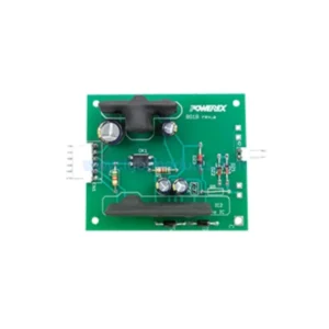
Voltage level shifting from logic to gate levels; Sufficient current for fast charging of gate capacitance; Electrical isolation between control and power stages; Over-current and short-circuit protection; Under-voltage lockout (UVLO) protection
2. Driver Topologies
Different driver architectures serve different application complexity and isolation requirements.
Comparison Table
| Driver Type | Isolation Method | Typical Features | Best For |
|---|---|---|---|
| Opto-Isolated | Optocoupler | Basic drive + UVLO | Industrial drives |
| Magnetic Isolated | Transformer | Integrated DC-DC | High-frequency designs |
| Coreless Transformer | CT Coupling | High CMR, compact | Motor drives, UPS |
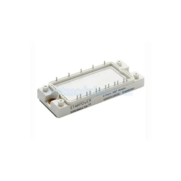
| Hybrid Module | Multi-channel | 6-pack drive + protection | Inverter systems |
Optocoupler-Based Drivers
Optically isolated gate drivers use light to transmit control signals across the isolation barrier.
• High common-mode transient immunity; Proven isolation technology; Wide availability of IC options; Suitable for medium-voltage systems
Magnetically Isolated Drivers
Transformer-coupled drivers use magnetic fields for signal and power transfer.
• High isolation voltage capability; Integrated DC-DC power supply options; Compact integrated solutions; Good for high switching frequencies
3. Key Protection Features
Modern IGBT drivers integrate multiple protection mechanisms to enhance system reliability.
Short-Circuit Protection
Desaturation detection monitors collector voltage to identify fault conditions and trigger safe shutdown.
• Vce(sat) monitoring with blanking time; Soft turn-off for fault conditions; Fault feedback to controller; Adjustable response thresholds
Over-Temperature and Under-Voltage
Additional protection layers prevent operation outside safe conditions.
• Under-voltage lockout on both primary and secondary sides; Over-temperature sensing and shutdown; Active Miller clamping; Fault status reporting
4. Design Considerations
Proper gate driver design is critical for reliable IGBT operation.
• Calculate required peak gate drive current; Select appropriate gate resistance for switching speed; Ensure adequate isolation creepage and clearance; Minimize parasitic inductance in gate loop; Provide proper decoupling and power supply filtering
5. Find the Right Solution for Your Application
Designing a reliable gate drive circuit is essential for IGBT-based converter performance. Explore isolated IGBT gate driver solutions with comprehensive protection features for industrial, renewable energy, and traction applications.
6. Frequently Asked Questions
1:Why is galvanic isolation necessary in IGBT gate drivers?
Galvanic isolation protects low-voltage control circuits from high-voltage power stages, ensures operator safety, and prevents ground loop issues. Isolation also enables proper operation of high-side switches in bridge topologies where the emitter voltage swings between ground and DC bus voltage. Isolation voltage ratings must meet applicable safety standards for your target application and voltage class.
2:What is desaturation protection and do I need it?
Desaturation (Vce-sat) protection detects short-circuit conditions by monitoring the collector-emitter voltage of the IGBT during conduction. When Vce exceeds a preset threshold, the driver initiates a controlled soft turn-off to prevent destructive di/dt. Desaturation protection is recommended for most applications, especially those with motor loads that can produce shoot-through faults or where output short circuits are possible.
3:How do I select the right gate resistance value?
Gate resistance controls the switching speed of the IGBT. Lower Rg values produce faster switching with lower switching losses but higher voltage overshoot and dv/dt, which can cause EMI issues and device stress. Higher Rg values reduce stress and EMI but increase switching losses. Start with the manufacturer recommended value in the datasheet, then optimize based on your specific requirements for efficiency, EMI compliance, and device stress margins.