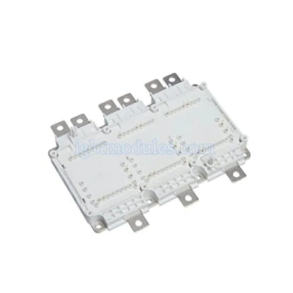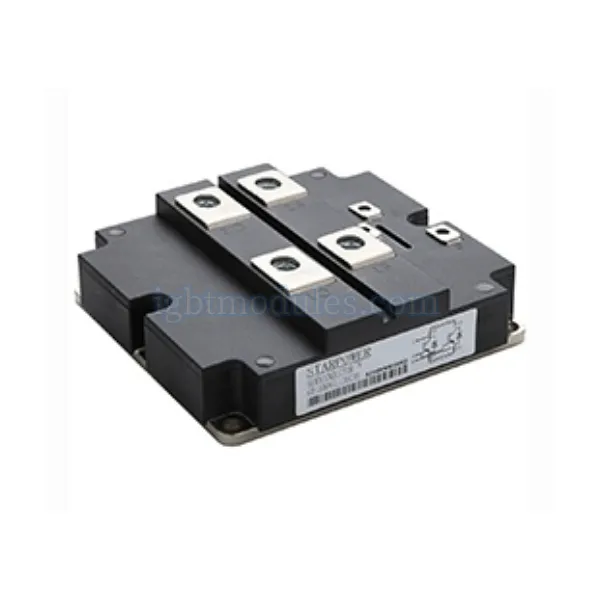

1. Bridge Rectifier Module Overview
Single-phase and three-phase configurations; Voltage ratings: 200V to 2000V; Current ratings: 10A to 500A; Integrated isolation and thermal interface; Standard industry footprints
2. Topology Options
Different circuit configurations address various input phase counts and rectification requirements.
Comparison Table
| Topology | Phases | Diodes | Typical Power Range |
|---|---|---|---|
| Half-Wave | 1 | 1 | Very low power |
| Full Bridge | 1 | 4 | 10W – 5kW |
| Three-Phase Bridge | 3 | 6 | 1kW – 100kW+ |
| PIM (Rect+Inverter) | 3 | 6 diodes + 6 IGBTs | 1kW – 50kW |
Single-Phase Bridges
Four-diode full-bridge rectifiers convert single-phase AC into pulsating DC.
• 4-diode full-bridge configuration; Common in low-power consumer and industrial supplies; Available in through-hole and SMD packages; Current range: 1A to 100A typical
Three-Phase Bridges
Six-diode three-phase bridges provide higher power rectification for industrial three-phase systems.
• 6-diode three-phase full-bridge; Higher power density than single-phase; Lower output ripple current; Used in motor drives and industrial power systems
3. Application Areas
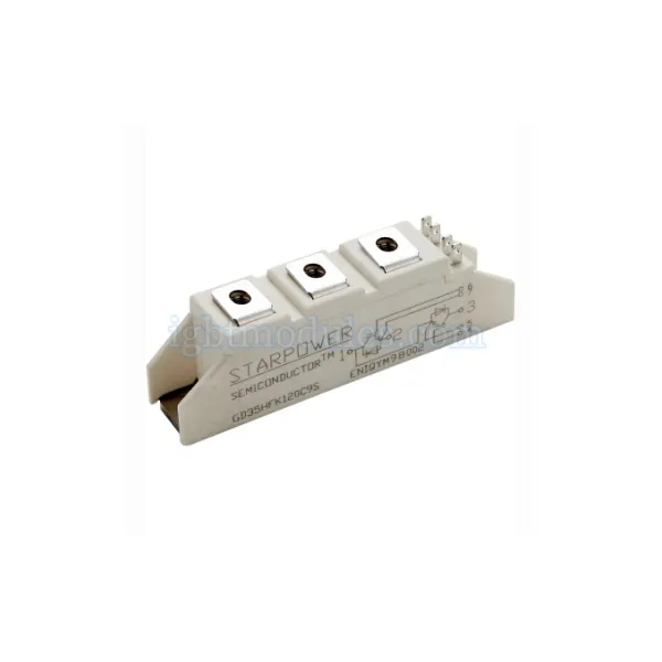
Bridge rectifier modules serve as front-end power conversion in many systems.
Industrial Power Supplies
DC power supplies for industrial equipment use bridge rectifiers at the input stage.
• Switch-mode power supply front-ends; Linear power supply rectification; Battery chargers; DC motor power supplies
Motor Drive Front-Ends
Variable frequency drives require a DC link, typically created by a three-phase bridge rectifier.
• VFD and VSD DC bus rectification; Servo drive power inputs; Elevator and crane drives; Conveyor systems
4. Design Guidelines
Proper selection and thermal design ensure reliable bridge rectifier operation.
• Calculate RMS and average current per diode; Apply adequate derating for voltage and current; Design proper heatsinking for total power loss; Consider inrush current limiting; Add appropriate input filtering for EMC compliance
5. Find the Right Solution for Your Application
Simplify your rectifier design with integrated bridge modules. Explore single-phase and three-phase bridge rectifier modules in various current and voltage ratings for efficient, compact power conversion.
6. Frequently Asked Questions
1:What are the advantages of bridge rectifier modules over discrete diodes?
Bridge rectifier modules offer reduced component count and PCB space, simplified assembly and inventory management, matched diode characteristics within the same package for balanced current sharing, improved thermal consistency since all diodes share the same substrate, and pre-configured topologies including single-phase, three-phase, and half-bridge that save design time. These benefits are especially valuable in volume production environments.
2:How do I choose between single-phase and three-phase bridge rectifiers?
Choose based on your input power source and power level. Single-phase full-wave bridge rectifiers with four diodes are used with single-phase AC mains for low-to-medium power applications typically up to several kilowatts. Three-phase 6-pulse bridge rectifiers with six diodes are used with three-phase AC supplies for higher power applications, offering lower ripple current, higher efficiency, and better utilization of the AC supply. For very high power, 12-pulse or 24-pulse configurations using multiple bridges can reduce input harmonics.
3:What is the ripple frequency of a bridge rectifier?
A single-phase full-wave bridge rectifier produces a ripple frequency equal to twice the input line frequency, for example 100Hz from a 50Hz input or 120Hz from a 60Hz input. A three-phase 6-pulse bridge rectifier produces ripple at six times the line frequency, which is 300Hz from 50Hz or 360Hz from 60Hz. Higher ripple frequency means smaller and less expensive filter capacitors are needed to achieve the same output voltage ripple specification.